
Skip to content
Local engineering & support in Egypt and the region
ENTRA DIGITAL TWIN STUDIO · 19 INTERACTIVE 3D SYSTEMS

Every ENTRA system, built to be explored.

Conveyors, elevators and handling equipment from ENTRA’s Egyptian workshops, as interactive 3D models you can turn, open up and run.
19 interactive 3D models
14 product families
8 engineering categories
Building conveyors since 2007
ENTRA ON SITE

See ENTRA systems at work

Footage from ENTRA projects: manufacturing, installing and running conveyor and material-handling systems in factories.
Request a quotation Watch on YouTube

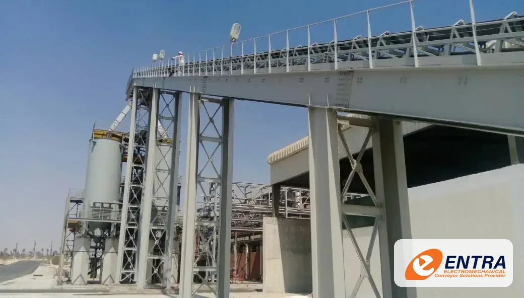
ENTRA bulk belt conveyor installation — video preview
CLIENTS

Multinational and Egyptian producers rely on ENTRA

From food and beverage to personal care, packaging and energy, our conveyor systems run in plants across Egypt, the Middle East and Africa.

  • Nestlé
  • Procter & Gamble
  • Unilever
  • Mondelēz International
  • Mars
  • Kellogg's
  • Tetra Pak
  • Shell
  • ABB
  • Electrolux
  • L'Oréal
  • Froneri
  • Bel
  • Almarai
  • Evyap
  • Elsewedy Electric
  • Danone
  • Juhayna
  • Beyti
  • Bericap
  • ARMA
  • SEDICO
  • Hassan Allam
  • AMI Förder- und Lagertechnik

Also trusted by Kraft Foods · Fine · Obour Land · Haidylena · Al Nasr Chemicals · Unitel · Olé · Harvest · Aroussa · Brego

Certified management systems

  • ISO 9001:2015Quality management
  • ISO 14001:2015Environmental management
  • ISO 45001:2018Occupational health & safety
  • SMETA 4-PillarSedex ethical trade audit

Sole agent of MODU System in Egypt

Since 2009 ENTRA has represented MODU System, the modular conveyor manufacturer founded in Singapore in 1995, supplying its chain, belt and aluminium conveyor platform with local engineering and support.

Explore the MODU platform →
A GOOD PLACE TO START

Let’s find the right solution for your factory

Answer four simple questions. We’ll suggest a suitable ENTRA solution, explain how it works and show you what to consider next. No engineering knowledge needed.
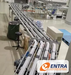
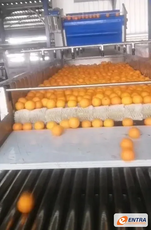
Modular conveyor carrying cartons
Modular conveying
Industrial roller conveyor
Roller handling
Screw conveyor equipment
Bulk handling
Question 1 of 4 About 1 minute
Choose one answer to continue.

Your result is a helpful starting recommendation. Our team will confirm the final design after reviewing your product, layout, capacity and operating conditions.

01 · COMPLETE PRODUCT PORTFOLIO

Browse ENTRA conveyor and handling systems

Filter by engineering category, search by system name or application, preview technical specifications and components, or launch any model directly in the interactive 3D studio.

  • SYS-01 Belt conveyors 2 variants

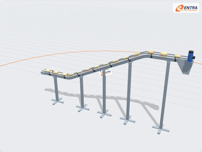
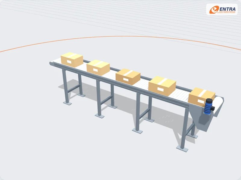
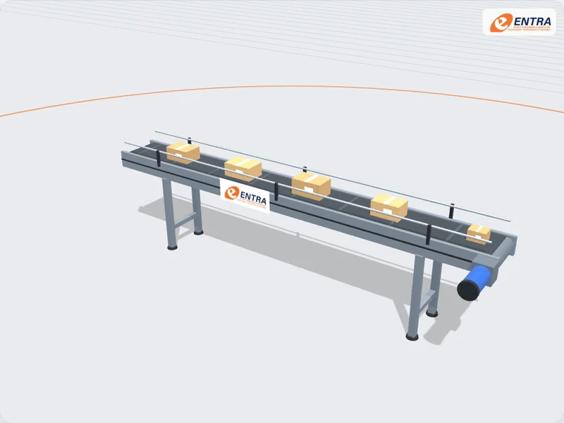
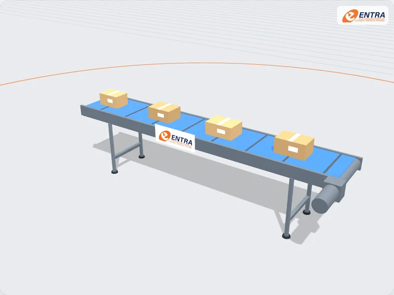
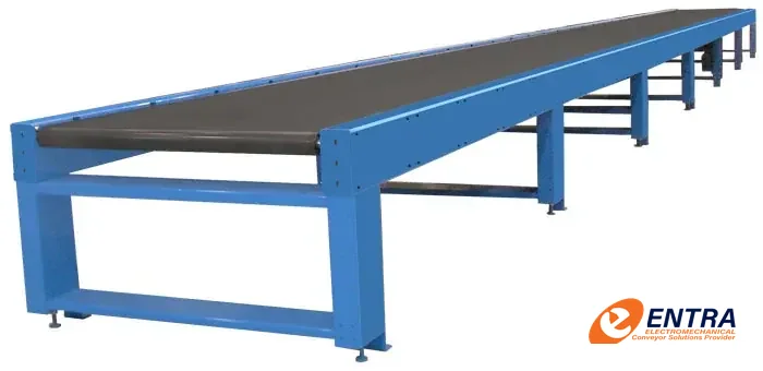
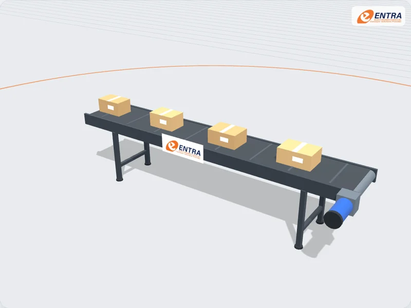
    Belt Conveyor

    A continuous belt runs over a drive drum and a tail drum to carry cartons, cases, bags and unit loads. Built flat or as a cleated incline between levels.

    Conveying element
    Flat belt selected for the product
    Typical loads
    Cartons, cases, bags, unit loads
    Packaging lines Warehouse flow Machine infeed
  • SYS-02 Roller conveyors 2 variants

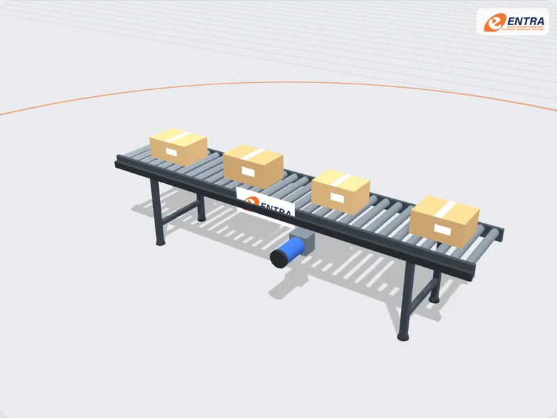
    Roller Conveyor

    Loads travel on a bed of rollers. Gravity sections use a slight slope or a manual push; powered sections drive the rollers for transport and accumulation.

    Conveying element
    Steel rollers on a side frame
    Typical loads
    Cartons, totes, flat-based loads, pallets
    Carton handling Accumulation Pallet flow
  • SYS-03 MODU chain & modular belt 5 variants

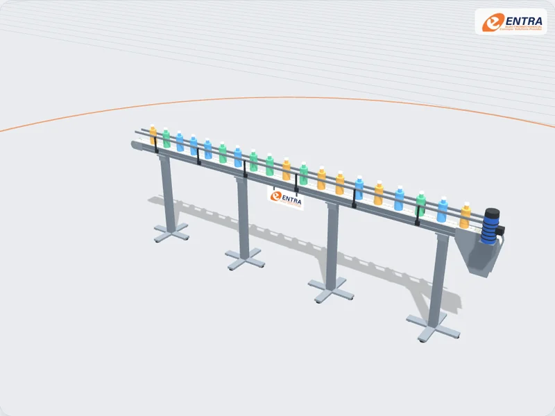
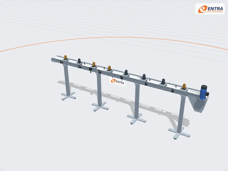
    MODU Straight Chain Conveyor

    An aluminium beam guides a plastic chain on low-friction slide rails. Five chain widths carry items from 15 mm to 500 mm wide.

    Chain width
    83 mm
    Pitch
    33.5 mm
    Packing lines Bottles and cans Assembly feeding
  • SYS-04 MODU chain & modular belt 4 variants

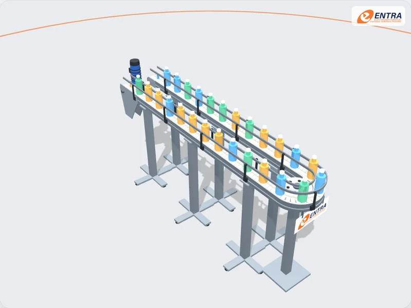
    MODU 180° Wheel Bend

    A free-turning wheel carries the chain round a tight radius. It has the lowest friction of any bend.

    Chain width
    83 mm
    Wheel bend radius
    160 mm
    U-turns in tight spaces Return loops Accumulation tables
  • SYS-05 MODU chain & modular belt 3 variants

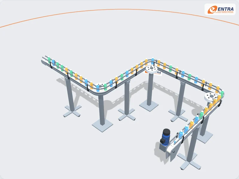
    MODU Flexible Layout

    One chain and one drive follow the route your floor allows. Wheel bends come in 30°, 45°, 60°, 90° and 180°.

    Chain width
    63 mm
    Wheel bend radius
    150 mm
    Routing round machines Linking work cells Buffer loops
  • SYS-06 MODU chain & modular belt 3 variants

    MODU Friction-Chain Incline

    A friction-top chain climbs up to 25° without the product slipping back. Plain chain is limited to about 7°.

    Chain width
    83 mm
    Chain type
    Friction top (TPE)
    Level changes Machine infeed Clearing walkways
  • SYS-07 MODU chain & modular belt 3 variants

    MODU Modular Belt Conveyor

    A plastic modular belt for wider and heavier products, in 315, 435 and 585 mm widths.

    Belt width
    435 mm
    Pitch
    45 mm
    Cartons and trays Multipacks End of line
  • SYS-08 MODU chain & modular belt 4 variants

    MODU MM3 Pallet System

    Products ride on pallets carrying RFID tags, so each one can be stopped, located and tracked through the line.

    Pallet size
    160 × 130 mm
    Max load per pallet
    10 kg
    Assembly lines Testing stations Track and trace
  • SYS-09 Belt conveyors Standard

    Aluminium-Profile Conveyor

    A conveyor built on slotted aluminium profiles, so guides, sensors and stands bolt on anywhere and the line is easy to extend or reconfigure.

    Frame
    Slotted aluminium profile
    Conveying element
    Belt or chain chosen for the product
    Assembly lines Packaging cells Machine linking
  • SYS-10 Stainless steel Standard

    Stainless-Steel Conveyor

    A conveyor with a stainless-steel structure and an open, cleanable frame for process areas where corrosion resistance and washdown matter.

    Frame
    Stainless steel, grade chosen per project
    Conveying element
    Belt chosen for product contact
    Food processing Beverage Wet areas
  • SYS-11 Vertical & elevation Standard

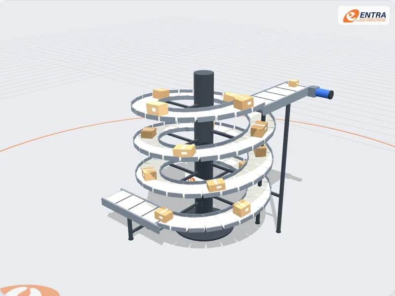
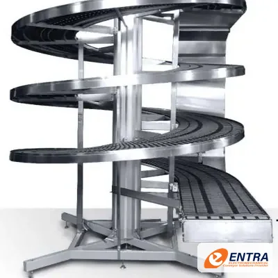
    Spiral Conveyor

    Products climb or descend on a continuous helical track around a central column, changing level in a small footprint without stopping the flow.

    Conveying element
    Continuous helical belt or chain track
    Typical loads
    Cartons, trays, cases, packs
    Level changes Cooling Buffering
  • SYS-12 Vertical & elevation Standard

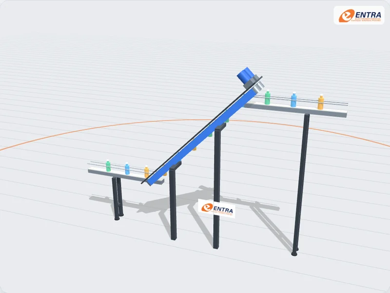
    Side-Gripper Conveyor

    Two opposing belts hold each container by its sides and carry it steeply up or down between conveyor levels, keeping it upright.

    Conveying element
    Two synchronised gripper belts
    Typical loads
    Bottles, cans, jars, rigid containers
    Bottling lines Can lines Walk-through access
  • SYS-13 Vertical & elevation Standard

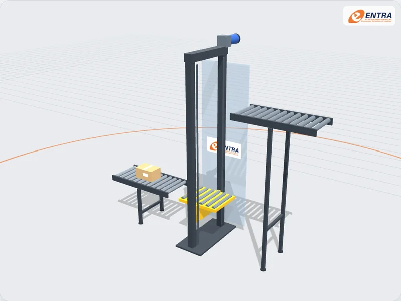
    Industrial Elevator

    A guided carriage lifts or lowers the load between two conveyor levels when a horizontal conveyor cannot bridge the height.

    Conveying element
    Guided lifting carriage
    Typical loads
    Cartons, crates, unit loads
    Floor-to-floor transfer Machine feeding Mezzanines
  • SYS-14 Bulk handling 2 variants

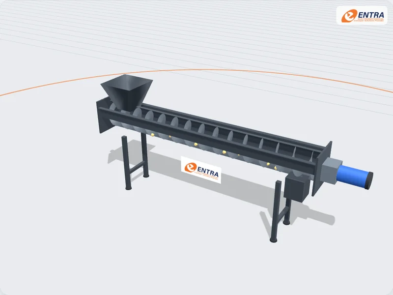
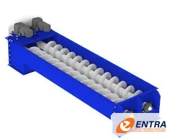
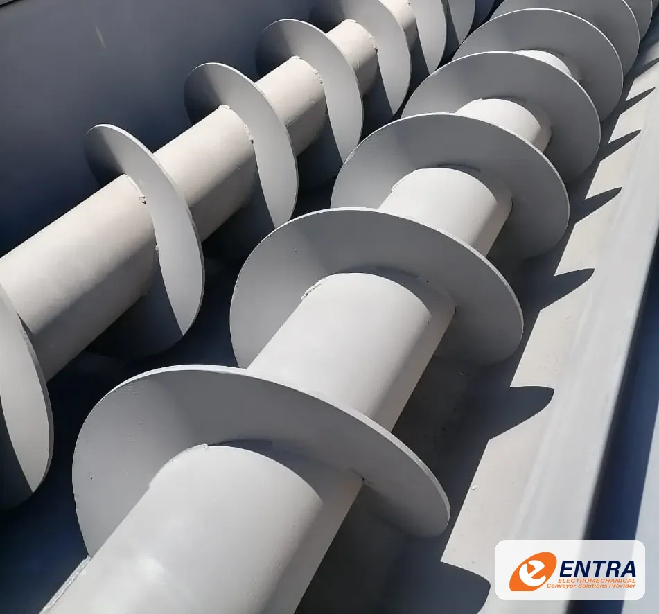
    Screw Conveyor

    A rotating helical flight pushes powders, grains and other bulk material along a closed casing from the inlet to the discharge.

    Conveying element
    Helical flight on a shaft
    Typical loads
    Powders, grains, granules, bulk solids
    Bulk transfer Dosing and feeding Process plants
  • SYS-15 Handling stations Standard

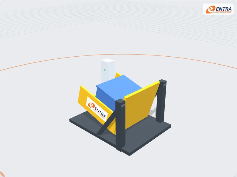
    Tilting Station

    A pivoting cradle holds the load and tilts it to a set angle for emptying, feeding or a change of orientation, then returns it.

    Conveying element
    Pivoting cradle on a fixed frame
    Typical loads
    Bins, containers, pallet loads
    Bin emptying Line feeding Load orientation
  • SYS-16 Handling stations Standard

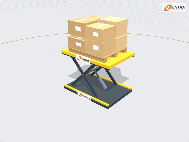
    Scissor Lift Table

    Crossed scissor arms raise and lower a level platform, bringing pallets and heavy loads to a safe working height or to the level of a conveyor.

    Conveying element
    Level platform on scissor arms
    Typical loads
    Pallets, bins, heavy unit loads
    Ergonomic workstations Pallet handling Level matching
  • SYS-17 Handling stations Standard

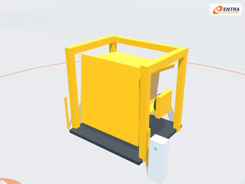
    Pallet Inverter

    A rotating clamp unit grips a full pallet load between two platens and turns it over, so the pallet can be exchanged or damaged goods recovered without hand restacking.

    Conveying element
    Clamping platens on a rotating unit
    Typical loads
    Full pallet loads
    Pallet exchange Hygiene areas Damaged load recovery
  • SYS-18 Handling stations Standard

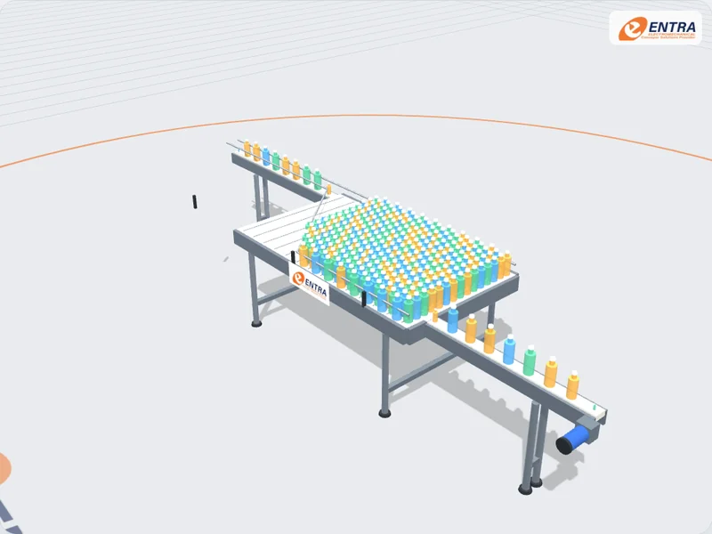
    Accumulation Table

    A wide moving bed holds products for a short time when the next machine stops, then guide rails funnel them back into single file so the line keeps running.

    Conveying element
    Wide modular belt bed
    Typical loads
    Bottles, cans, jars, containers
    Bottling lines Filler and labeller buffers Packing lines
  • SYS-19 Line integration Standard

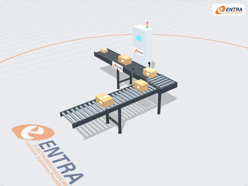
    Conveyor Line Integration

    Conveyor sections, a right-angle transfer, sensors and a control panel work as one line, so product flow is coordinated between machines.

    Conveying element
    Belt and roller sections with a transfer
    Typical loads
    Depends on the connected machines
    New production lines Line extensions Controls upgrades
02 · INTERACTIVE 3D SHOWCASE

See how each system works

Drag to rotate, pinch or Ctrl + scroll to zoom, and tap the orange points to identify the main components. Use Explode to separate the assemblies and Fullscreen for a closer look.

BELT CONVEYORS · MODEL 1 / 19
3D INTERACTIVE DIGITAL TWIN

Loading 3D scene…

04 · PRODUCT FAMILIES IN DETAIL

How each ENTRA system works and where it is used

Operating principle, typical applications, main components, configurations and the design basis ENTRA engineers use for each of the 14 product families.

FAMILY // 01 1 interactive 3D models

Belt Conveyor Systems

Continuous belt transport for cartons, cases, packaged products and suitable unit loads across production, packing and distribution lines.

Description and operating principle

A belt conveyor carries products on a continuous moving belt supported by a frame and driven through a pulley arrangement. Belt material, width, speed, support, tracking and transfer geometry are selected for the product and operating environment. This page describes the equipment family; it is not a fixed standard design.

Belt Conveyor A continuous belt runs over a drive drum and a tail drum to carry cartons, cases, bags and unit loads. Built flat or as a cleated incline between levels.

Typical applications

  • Cartons and cases. Transport packaged goods between production, inspection, packing and dispatch operations.
  • Production-line transfer. Connect machines and workstations with a continuous conveying surface.
  • Inclined transport. Move suitable products between levels when belt surface, cleats and product stability are appropriate.
  • Inspection and packing. Provide a stable conveying surface for manual or automated inspection and packing tasks.

Available configurations

  • Horizontal belt conveyor. Straight conveying path for unit loads and packaged products.
  • Inclined / declined belt. Elevation change selected around product stability, belt surface and transfer geometry.
  • Cleated belt. Cleats or profiles assist product retention on suitable inclines and controlled spacing duties.
  • Curved / transfer arrangement. Layout-specific curves, nose transfers or cross transfers where the selected belt system supports them.

Main components

  • Drive unitA gearmotor turns the head drum that pulls the belt.
  • Conveyor beltCarries the product; the belt type is chosen for the load.
  • Tail drumReturns the belt and is used to tension and track it.
  • Side frameSupports the belt bed, drums and guides.

Technical design basis

Belt width
Selected from product footprint, edge clearance and loading pattern.
Belt speed
Set from target throughput, product pitch and connected-machine cycle time.
Belt material
Selected for product contact, abrasion, temperature, cleaning chemicals and applicable compliance requirements.
Drive duty
Motor, gearbox, pulley and starting method sized from load, incline, friction and duty cycle.
Frame & supports
Designed for span, loading, environment, floor fixing and access requirements.

The gallery photos are ENTRA portfolio references from the belt-conveyor category. No universal belt speed, capacity, width or load rating is published here because these depend on the selected belt, drive, frame and application.
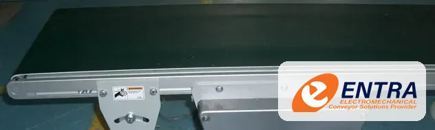
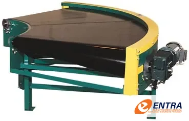
Belt conveyor — ENTRA gallery reference Belt conveyor frame and conveying path Belt conveyor installation detail
FAMILY // 02 1 interactive 3D models

Roller Conveyor Systems

Gravity and powered roller conveyor arrangements for conveying, accumulation, transfer and distribution of compatible unit loads.

Description and operating principle

Roller conveyors support products on a series of rotating rollers. Gravity versions rely on slope and product momentum; powered versions drive rollers directly or through belts, chains or line shafts. Roller pitch, diameter, frame and drive zones must suit the load base and product geometry.

Roller Conveyor Loads travel on a bed of rollers. Gravity sections use a slight slope or a manual push; powered sections drive the rollers for transport and accumulation.

Typical applications

  • Carton and tote handling. Move rigid-base cartons, totes and containers through packing and dispatch areas.
  • Accumulation. Buffer products between processes using controlled or zero-pressure zones where specified.
  • Pallet and heavy unit loads. Handle compatible palletized loads using appropriately engineered roller sizes, frames and drives.
  • Transfer and sorting interfaces. Connect conveyor sections with transfer units, stops and diverters designed for the load.

Available configurations

  • Gravity roller. Non-powered roller bed for compatible products and layouts with suitable slope or manual push.
  • Powered roller. Motor-driven zones for controlled movement and line integration.
  • Accumulation conveyor. Buffered zones using control logic selected for product and process requirements.
  • Curves and transfers. Direction changes and cross transfers designed around load footprint and stability.

Main components

  • RollersThe load rolls on closely spaced rollers.
  • Side frameHolds the roller axles at a fixed pitch.
  • DrivePowers the rollers through the drive train in the guard.
  • Drive guardCovers the roller drive along the frame.

Technical design basis

Roller pitch
Selected so the load is supported by sufficient rollers throughout travel.
Roller diameter & wall
Selected from load, impact, span, duty and bearing requirements.
Load capacity
Calculated for the actual load distribution, roller count, frame span and support arrangement.
Drive arrangement
Gravity, chain, belt or motorized roller solution selected for control and duty.
Accumulation control
Zone logic and sensor placement defined by product flow and downstream acceptance.

Roller conveyor images are from ENTRA’s roller-conveyor gallery. Pallet duty, carton duty and accumulation behavior require different design checks; the same roller layout should not be assumed suitable for every load.
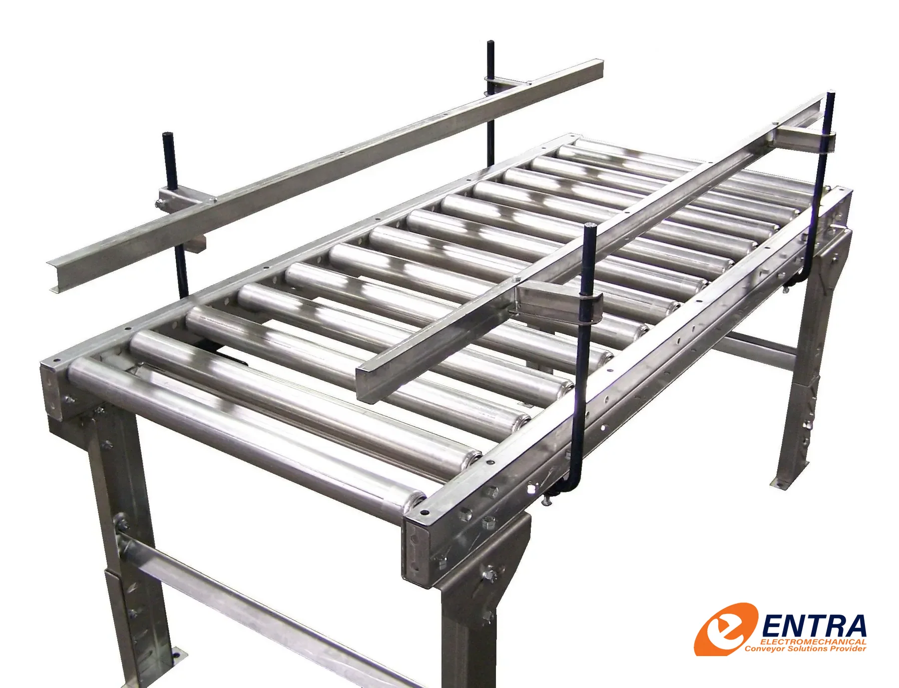
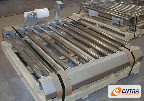
Roller conveyor — ENTRA gallery reference Roller conveyor bed and roller layout Roller conveyor system installation
FAMILY // 03 6 interactive 3D models

MODU Plastic-Chain Conveyor Systems

Modular plastic-chain conveyor platforms for compact product handling, straight runs, curves and engineered line layouts.

Description and operating principle

MODU plastic-chain systems use modular links running over compatible wear strips and support profiles. The V22 catalogue identifies aluminium plastic-chain families MP, MS3, MM3, ML2 and MX2, plastic-belt families MT2, MR2 and MF2, pallet families and stainless families. Select the family and polymer only after checking product, duty and environment.

MODU Straight Chain Conveyor An aluminium beam guides a plastic chain on low-friction slide rails. Five chain widths carry items from 15 mm to 500 mm wide.
MODU 180° Wheel Bend A free-turning wheel carries the chain round a tight radius. It has the lowest friction of any bend.
MODU Flexible Layout One chain and one drive follow the route your floor allows. Wheel bends come in 30°, 45°, 60°, 90° and 180°.
MODU Friction-Chain Incline A friction-top chain climbs up to 25° without the product slipping back. Plain chain is limited to about 7°.
MODU Modular Belt Conveyor A plastic modular belt for wider and heavier products, in 315, 435 and 585 mm widths.
MODU MM3 Pallet System Products ride on pallets carrying RFID tags, so each one can be stopped, located and tracked through the line.

Typical applications

  • Packaged product flow. Convey bottles, packs, cartons or components where chain width, surface and transfer geometry match the product.
  • Curved line routing. Use compatible chain and guide arrangements to route product around production equipment.
  • Assembly and process lines. Connect workstations, filling, labelling, inspection and packing operations.
  • Pallet and carrier handling. Use the catalogue pallet families only with a design matched to carrier geometry and loading.

Available configurations

  • Aluminium plastic-chain. MODU MP, MS3, MM3, ML2 and MX2 catalogue families, selected by width and layout.
  • Plastic-belt families. MT2, MR2 and MF2 families as catalogued; belt construction and duty must be confirmed.
  • Pallet conveyor families. MP, MM3, ML2 and MDP pallet families, selected for carrier and load geometry.
  • Stainless families. DS3, DM3, DL2, DX2, DT2, DR2 and DF2 as listed in the V22 catalogue.

Main components

  • End drive unitPulls the chain. Traction up to 1000 N.
  • MM3 plain chain83 mm wide POM links, 33.5 mm pitch.
  • Conveyor beamAnodised aluminium with T-slots, supplied in 3 m lengths.
  • Guide railKeeps products on track; brackets clamp into the T-slot.
  • Idler endTurns the chain back into the return track.

Technical design basis

MODU MP (POM)
35 mm chain width; 2,000 N tensile strength at 20°C; 500 N maximum working tension; 5–40 m/min recommended speed; 150 mm minimum radius; 25.4 mm pitch; -10 to +60°C; max length 20 m layout-dependent.
MODU MS3 (POM)
63 mm chain width; 3,000 N tensile strength at 20°C; 700 N maximum working tension; 5–50 m/min; 150 mm minimum radius; 25.4 mm pitch; -10 to +60°C; max length 30 m layout-dependent.
MODU MM3 (POM)
83 mm chain width; 4,000 N tensile strength at 20°C; 1,000 N maximum working tension; 5–50 m/min; 160 mm minimum radius; 33.5 mm pitch; -10 to +60°C; max length 30 m layout-dependent.
MODU ML2 (POM)
140 mm chain width; 5,000 N tensile strength at 20°C; 1,200 N maximum working tension; 5–50 m/min; 200 mm minimum radius; 44.5 mm pitch; -10 to +60°C; max length 30 m layout-dependent.
MODU MX2 (POM)
220 mm chain width; 5,000 N tensile strength at 20°C; 1,200 N maximum working tension; 5–50 m/min; 500 mm minimum radius; 44.5 mm pitch; -10 to +60°C; max length 30 m layout-dependent.

Numerical values above are transcribed from the supplied MODU Product Catalogue V22 technical reference for POM chain. PP chain data differ. These catalogue reference values are not an application approval; confirm exact material, duty, load, temperature, speed, layout and series with ENTRA. Catalogue family page references are recorded in MODU-CATALOGUE-V22-REFERENCE.md.
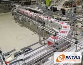
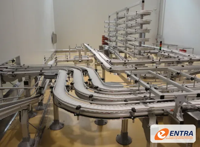
Modular conveyor — ENTRA gallery reference Plastic-chain conveyor components Modular conveyor layout reference
FAMILY // 04 1 interactive 3D models

Aluminium-Profile Conveyor Systems

Aluminium-profile conveyor frames and modular structures for production, assembly, inspection and material-transfer stations.

Description and operating principle

Aluminium-profile conveyors use modular extruded profiles and compatible brackets, supports and guarding to create configurable conveyor frames. The conveying medium may be selected separately—such as belt or modular chain—so frame material alone does not define the conveyor’s load or performance.

Aluminium-Profile Conveyor A conveyor built on slotted aluminium profiles, so guides, sensors and stands bolt on anywhere and the line is easy to extend or reconfigure.

Typical applications

  • Assembly workstations. Provide modular conveyor sections alongside manual or automated assembly processes.
  • Inspection and testing. Support product movement through checking, testing and quality-control stations.
  • Machine connections. Connect compact machines and work cells with configurable frame and transfer sections.
  • Reconfigurable lines. Use modular construction where future adjustment, guarding or accessory mounting is important.

Available configurations

  • Profile frame belt conveyor. Aluminium profile structure with a separately selected belt and drive arrangement.
  • Profile frame chain conveyor. Modular frame supporting a compatible plastic-chain conveying path.
  • Workstation conveyor. Conveyor combined with adjustable supports, guides and operator interfaces.
  • Machine infeed / outfeed. Compact frame and transfer sections matched to adjacent equipment.

Main components

  • Slotted aluminium profileAccessories clamp into the slots anywhere along the frame.
  • Adjustable guide railSet to the product width.
  • Drive unitCompact gearmotor on the head end.
  • Conveying beltBelt or chain is chosen for the product.

Technical design basis

Profile series & section
Selected from structural load, span, stiffness and accessory compatibility.
Conveying surface
Belt, chain or roller type selected independently for product contact and process duty.
Frame deflection
Checked for product load, conveyor span, support spacing and dynamic operation.
Mounting & accessories
Footing, brackets, guarding, guides and sensor mounts coordinated with the machine layout.

The supplied gallery has a dedicated aluminium-conveyors category with four references. The images show aluminium conveyor structures; they should not be read as proof of a particular profile series or load rating.
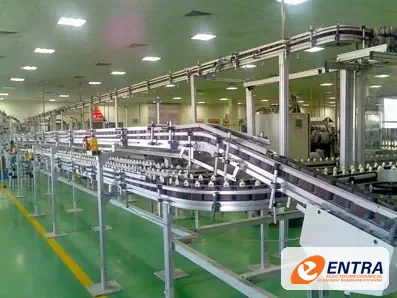
Aluminium conveyor — ENTRA gallery reference Aluminium frame conveyor structure Aluminium conveyor support and frame detail
FAMILY // 05 1 interactive 3D models

Stainless-Steel Conveyor Systems

Stainless conveyor structures and conveying arrangements designed around defined product-contact, cleaning and process-environment requirements.

Description and operating principle

Stainless-steel conveyors are selected where corrosion resistance, cleaning access, product-contact requirements or process conditions call for stainless construction. Stainless steel alone does not make a conveyor hygienic: geometry, weld finish, drainage, seals, bearings, belt materials and cleaning procedures all matter.

Stainless-Steel Conveyor A conveyor with a stainless-steel structure and an open, cleanable frame for process areas where corrosion resistance and washdown matter.

Typical applications

  • Food and beverage. Convey compatible packaged or process products in environments with defined cleaning and sanitation needs.
  • Pharmaceutical and personal care. Support controlled product transfer where materials, cleanability and documentation are specified by the process owner.
  • Washdown areas. Use suitable construction details and components where washdown is part of the operating procedure.
  • Corrosive environments. Select grade, finish and non-metallic components against the actual chemical exposure.

Available configurations

  • Stainless belt conveyor. Belt conveying with stainless structure and selected product-contact materials.
  • Stainless modular chain. Plastic-chain conveying on stainless support and frame construction.
  • Stainless roller conveyor. Roller bed and frame designed for the required process environment.
  • Custom process conveyor. Application-specific frame, guards, drains, supports and interfaces.

Main components

  • Stainless-steel frameOpen construction for cleaning access.
  • Product-contact beltBelt material is selected for the product and cleaning.
  • Drive unitDrive selected for the washdown conditions.
  • Round legs, adjustable feetFewer flat surfaces where residue can collect.

Technical design basis

Stainless grade
Selected from corrosion exposure and cleaning chemistry; grade is not assumed.
Surface finish & welds
Specified for cleanability, product-contact requirements and customer acceptance criteria.
Cleaning regime
Water, foam, chemical concentration, temperature, pressure and frequency defined by the user.
Seals & components
Bearings, motors, fasteners, belts and feet checked for the same environment.

No GMP, FDA, IP, ATEX or other compliance claim is implied. Customer standards and required documentation must be identified and reviewed for the specific project.
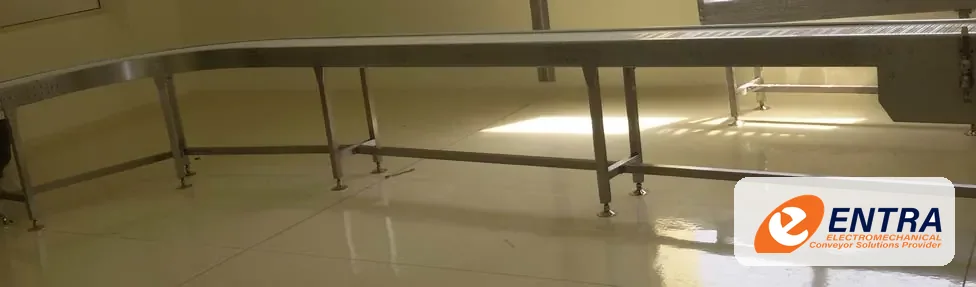
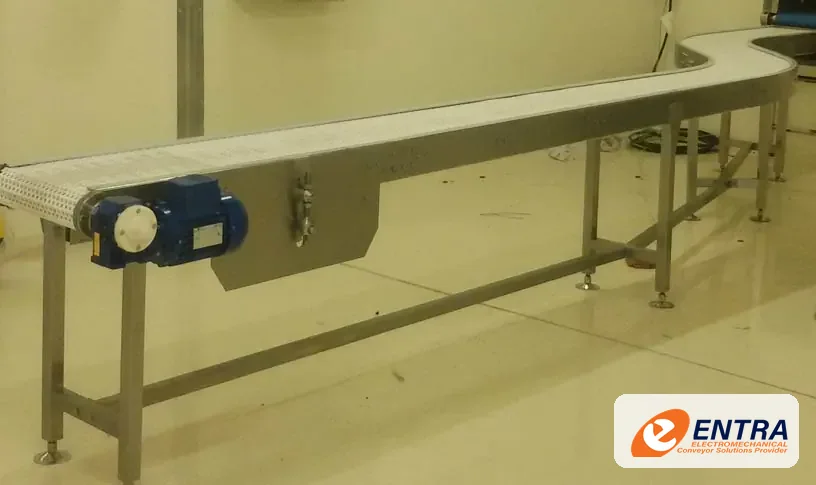
Stainless conveyor — ENTRA gallery reference Stainless conveyor equipment reference Stainless conveyor fabrication detail
FAMILY // 06 1 interactive 3D models

Spiral Conveyor Systems

Continuous vertical conveying for production lines that need elevation, accumulation or controlled cooling within a compact footprint.

Description and operating principle

An industrial spiral conveyor transfers products between elevations while maintaining a continuous conveying path. Depending on the belt, product and process, a spiral can be used for elevation, lowering, accumulation, cooling or buffering. The final design is selected around the product and the line—not from a generic height claim.

Spiral Conveyor Products climb or descend on a continuous helical track around a central column, changing level in a small footprint without stopping the flow.

Typical applications

  • Vertical elevation. Move cartons, trays, cases or suitable packaged products between production levels while preserving a continuous flow.
  • Cooling and conditioning. Create a long conveying dwell path for bakery, packaged food or other temperature-conditioning processes when the process and belt materials are suitable.
  • Accumulation and buffering. Use a spiral layout to add controlled product residence time and buffer adjacent processes where the line concept permits.
  • Floor-space constrained lines. Use vertical space to connect equipment across mezzanines, platforms or multiple production levels.

Available configurations

  • Elevation spiral. Continuous upward transfer between floor levels or production platforms.
  • Lowering spiral. Controlled downward transfer where product stability and discharge geometry allow.
  • Accumulation spiral. Extended conveying path used as a buffer between processes.
  • Cooling / conditioning spiral. Long residence path configured around product temperature, air flow and sanitation requirements.

Main components

  • Helical trackProducts keep moving while they change level.
  • Central columnCarries the track on radial arms.
  • InfeedProducts enter at the lower level.
  • Drive and outfeedOne drive moves the whole track; products leave at the top.

Technical design basis

Product envelope
Dimensions, mass, stability, package base and allowable contact surface.
Vertical travel
Infeed/outfeed elevations and required elevation change.
Spiral geometry
Tower diameter, belt path, curve geometry and available footprint.
Operating duty
Throughput, product pitch, accumulation target and operating hours.
Belt / chain and environment
Selected from product, temperature, cleaning and wear requirements.

Spiral capacity, maximum elevation, belt speed, product loading and temperature suitability are project-specific. ENTRA confirms these after reviewing the product, layout, belt selection, drive duty and operating environment. No universal capacity or height is assumed on this page.
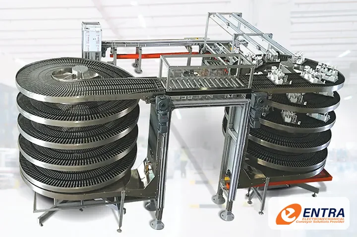
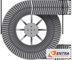
Spiral conveyor installation with continuous helical conveying path Spiral conveyor layout and curve configuration reference Industrial spiral conveyor tower
FAMILY // 07 1 interactive 3D models

Side-Gripper Conveyor Systems

Opposed gripping belts hold suitable products at their sides to move them vertically, invert them or connect different conveyor levels.

Description and operating principle

A side-gripper conveyor uses two synchronized, opposing belts or gripping elements to hold a product along its sides while it is transferred. It is useful where a conventional base-supporting conveyor cannot provide the required vertical path or where the product needs to be presented in a controlled orientation. Grip geometry and pressure must be matched to the actual container.

Side-Gripper Conveyor Two opposing belts hold each container by its sides and carry it steeply up or down between conveyor levels, keeping it upright.

Typical applications

  • Bottle and container elevation. Transfer suitable bottles, cans, jars and rigid containers upward between conveyor levels.
  • Lowering and level changes. Move containers downward into downstream equipment, packaging lines or accumulation zones.
  • Rinsing and inversion concepts. Where required, a purpose-designed arrangement can turn or invert compatible products for a defined process step. This is application-specific, not an inherent feature of every side-gripper.
  • Space-saving line integration. Route product vertically to free floor area, pass over or around equipment and connect separated production levels.

Available configurations

  • Vertical elevator. Upward product transfer between conveyor levels.
  • Vertical lowerator. Downward transfer while maintaining side control.
  • Variable-width grip. Adjustment approach selected for the product size range and changeover frequency.
  • Process-specific inversion. Custom orientation or inversion arrangement after checking product and process requirements.

Main components

  • Gripper beltsTwo belts hold each container by its sides.
  • Belt drivesEach belt is driven so both run at the same speed.
  • Infeed conveyorContainers arrive in single file.
  • Outfeed conveyorContainers are released upright at the new level.

Technical design basis

Container geometry
Height, diameter/width, shoulder profile, mass and centre of gravity.
Grip interface
Belt material, contact length, grip gap, friction and allowable deformation.
Vertical travel
Required elevation, line speed, product pitch and transfer sequence.
Drive synchronization
Matched speed and coordinated operation of opposing grip elements.
Safety & guarding
Access protection, interlocks, emergency stops and jam recovery.

Grip dimensions, pressure, belt speed and achievable throughput depend on the actual container and line layout. Fragile, tapered, wet, slippery or highly variable products require trials or engineering review before a final design is selected. The gallery includes one ENTRA gripper reference plus separate general elevator references; the latter are not presented as side-gripper installations.
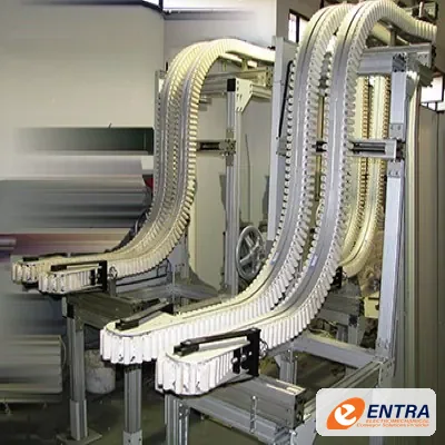
ENTRA side-gripper conveyor reference from the supplied project gallery
FAMILY // 08 1 interactive 3D models

Industrial Elevator & Lowerator Systems

Purpose-designed vertical transfer equipment for moving compatible products or loads between conveyor levels.

Description and operating principle

Industrial elevators and lowerators transfer products vertically when a horizontal conveyor cannot bridge the required level change. The lifting principle may use a platform, carrier, cleat, bucket, gripper or other product-specific support. The equipment principle must be selected from the load and transfer duty rather than inferred from the word elevator.

Industrial Elevator A guided carriage lifts or lowers the load between two conveyor levels when a horizontal conveyor cannot bridge the height.

Typical applications

  • Production floor level changes. Transfer compatible products between conveyors at different elevations.
  • Machine feeding and discharge. Present products to elevated or recessed machinery with controlled transfer.
  • Vertical buffering. Use a suitable carrier or platform arrangement where intermediate buffering is required.
  • Space-constrained layouts. Use vertical movement to reduce long ramps or avoid obstructing floor-level traffic.

Available configurations

  • Platform elevator. Lift table or platform for compatible discrete loads.
  • Continuous-flow elevator. Carrier-based continuous transfer where the product and duty support it.
  • Lowerator. Controlled downward transfer between line levels.
  • Special-purpose lift. Custom carrier, gripper or transfer concept after product assessment.

Main components

  • Lifting carriageTakes the load, travels on the mast guides and hands it over.
  • Guide mastColumns with guide rails keep the carriage aligned.
  • Lifting driveRaises and lowers the carriage.
  • Lower level conveyorFeeds the load onto the carriage.
  • Upper level conveyorReceives the load at the new height.

Technical design basis

Lift height & travel
Defined from floor levels, machine interfaces and installation envelope.
Rated load
Established from product mass, carrier mass, dynamic effects and safety design.
Cycle / throughput
Calculated from travel, loading, unloading, dwell and control sequence.
Safety functions
Defined by risk assessment, access conditions and applicable machinery requirements.

The ENTRA gallery includes two elevator references. They are shown as general elevator equipment and are not labelled as side-gripper systems. No rated load or travel speed is assumed.
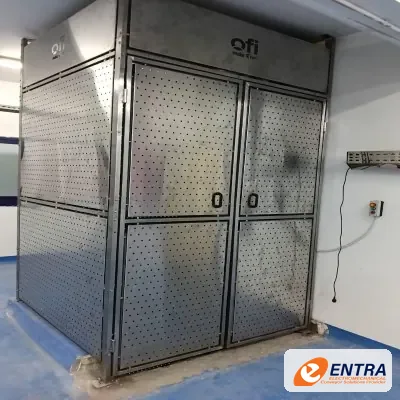
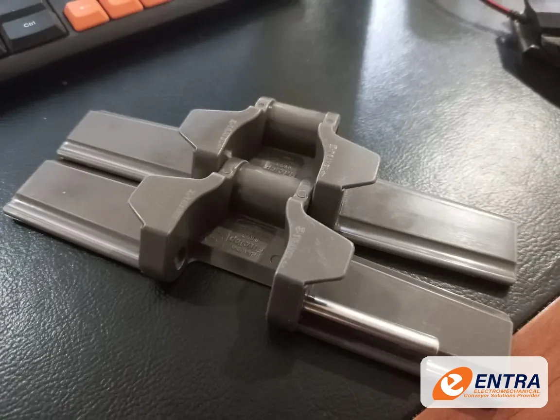
Industrial elevator — ENTRA gallery reference Vertical transfer equipment reference
FAMILY // 09 1 interactive 3D models

Screw & Auger Conveyor Systems

Meter, feed and transfer powders, granules and suitable bulk solids using a rotating helical flight in a trough or tube.

Description and operating principle

A screw conveyor moves bulk material along a casing by rotating a helical flight around a shaft—or by using a shaftless spiral in suitable applications. It can provide horizontal or inclined conveying, controlled feeding and transfer between process stages. Selection depends heavily on the material properties and the required duty.

Screw Conveyor A rotating helical flight pushes powders, grains and other bulk material along a closed casing from the inlet to the discharge.

Typical applications

  • Powders and fine materials. Transfer suitable flour, mineral powders, additives and other free-flowing or conditioned fine materials in an enclosed conveying path.
  • Granules and pellets. Move suitable plastic pellets, grains, seeds and granular products between storage, dosing and process equipment.
  • Metering and feeding. Use a screw feeder or variable-speed drive to support controlled feeding where the material and required accuracy permit.
  • Process and bulk transfer. Connect hoppers, silos, mixers, bagging equipment and production machinery with horizontal or inclined screw arrangements.

Available configurations

  • U-trough screw. Openable or covered trough arrangement for accessible process and bulk transfer duties.
  • Tubular screw. Enclosed tube arrangement where containment and routing requirements favour a tubular casing.
  • Screw feeder. Hopper-mounted feeding arrangement designed around material flow and required discharge control.
  • Twin-screw arrangement. Parallel screw configuration for selected feeding, mixing or difficult-flow applications after process review.

Main components

  • Screw flightAs it turns, the helix pushes material along the casing.
  • U-troughEncloses the material; covers are removed in this view.
  • InletMaterial is fed in from a hopper, silo or process outlet.
  • DischargeMaterial leaves at the end of the screw.
  • DriveA gearmotor turns the screw shaft.

Technical design basis

Material bulk density
Measured or supplied bulk density and its variation during operation.
Particle and flow behaviour
Particle size, cohesion, moisture, abrasiveness, temperature and tendency to bridge.
Screw geometry
Flight diameter, pitch, shaft/shaftless design, trough or tube and fill ratio.
Duty and inclination
Mass/volume flow, conveying length, inclination, start-up and operating hours.
Wear and containment
Liners, seals, bearings, cleanout, dust containment and material compatibility.

Screw conveyor capacity is not inferred from diameter alone. It depends on material bulk density and flow behaviour, flight geometry, pitch, speed, fill ratio, inclination and duty. Abrasive, sticky, hot, combustible or food-contact materials require specific material, sealing, guarding and process review.
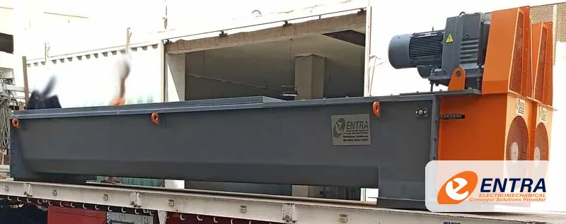
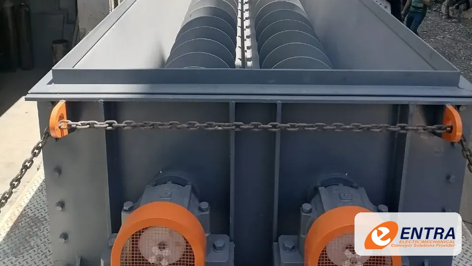
Industrial screw conveyor assembly Twin screw conveyor trough arrangement Screw conveyor helical flight detail
FAMILY // 10 1 interactive 3D models

Tilting & Inverting Stations

Engineered stations for controlled tipping, tilting or reorientation of compatible products, containers and loads.

Description and operating principle

Tilting and inverting stations change the orientation of a load to support emptying, access, assembly, inspection or process transfer. The mechanism may use a pivoting cradle, powered table, clamp or purpose-built fixture. Product retention and controlled movement are central to safe design.

Tilting Station A pivoting cradle holds the load and tilts it to a set angle for emptying, feeding or a change of orientation, then returns it.

Typical applications

  • Container and bin tipping. Tip compatible bins or containers into hoppers, feeders or process equipment.
  • Product reorientation. Rotate or tilt products for inspection, assembly or downstream handling.
  • Process loading and unloading. Present parts or materials to a machine or workstation at a controlled angle.
  • Ergonomic handling. Reduce manual handling where a mechanized tilt station is suitable and risk-assessed.

Available configurations

  • Bin tipper. Cradle or fixture for controlled tipping of a compatible bin or container.
  • Tilting table. Pivoting platform to present a load at a defined angle.
  • Inverting fixture. Purpose-built retention arrangement to rotate a component or carrier.
  • Custom handling station. Mechanism, guarding and controls designed around the actual product and task.

Main components

  • Tilting cradleHolds the load securely while it tilts.
  • Pivot bearingsThe cradle rotates about this axis.
  • Base frameAnchored to the floor to take the tilting forces.
  • Operator controlsTilt and return are started from the control station.

Technical design basis

Maximum load & centre of gravity
Established from the actual load and fixture, including dynamic effects.
Tilt angle / rotation
Defined from process requirements, clearance and product retention.
Actuation
Hydraulic, pneumatic, electric or mechanical drive selected by force, motion and environment.
Safety & guarding
Risk-assessed restraints, interlocks, access controls and safe loading method.

The gallery category contains tilting-station equipment references. Do not infer a rated load, tilt angle or safety category from photographs; these are determined by the project design and risk assessment.
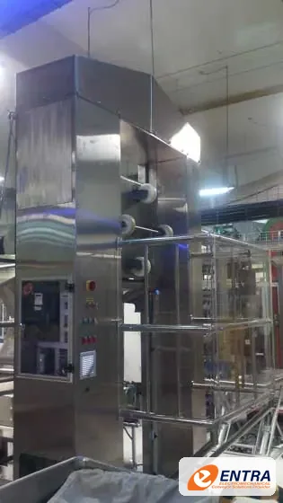
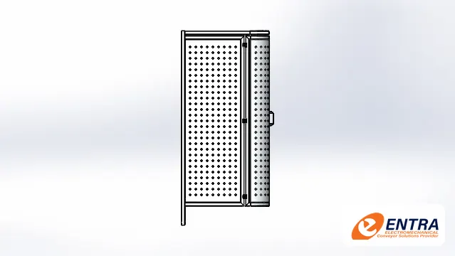
Tilting station — ENTRA gallery reference Tilting equipment structure Tilting mechanism reference
FAMILY // 11 1 interactive 3D models

Scissor Lift Tables

Scissor lift tables that raise pallets and heavy loads to a safe working height or to the level of a conveyor or machine.

Description and operating principle

A scissor lift table raises and lowers a level platform on crossed scissor arms driven by a lifting cylinder. It brings pallets, bins and heavy unit loads to a comfortable working height, matches the level of a conveyor or machine, or helps loading at different heights. Platform size, stroke, lifting drive and safety devices are selected for the load and the workplace.

Scissor Lift Table Crossed scissor arms raise and lower a level platform, bringing pallets and heavy loads to a safe working height or to the level of a conveyor.

Typical applications

  • Ergonomic workstations. Keep operators working at a comfortable height while a pallet is built up or emptied.
  • Conveyor and machine level matching. Lift loads to the height of a conveyor, press or packing machine.
  • Pallet and bin handling. Raise and lower pallets, bins and heavy unit loads in production and storage areas.

Available configurations

  • Single scissor. One pair of scissor arms for moderate lifting heights.
  • Pit-mounted table. Platform sits flush with the floor when lowered for pallet truck access.
  • Table with conveyor deck. Roller or belt deck on the platform to transfer loads at the lifted level.

Main components

  • Load platformCarries the pallet or load and stays level while it rises.
  • Scissor armsCrossed arms extend to raise the platform.
  • Lifting cylinderPushes the scissor arms apart to lift the load.
  • Base frameSits on the floor or in a pit, carrying the scissor pivots.

Technical design basis

Platform size
Selected from the load footprint and handling access.
Rated load & stroke
Established from the actual load and the required height range.
Lifting drive
Selected for load, speed and duty cycle.
Safety
Edge protection, guarding and controls defined for the installation.

No photo of an ENTRA lift table was supplied, so this page shows ENTRA's 3D model. Capacities, heights and speeds are defined per project and are not implied here.

Scissor lift table — ENTRA 3D model
FAMILY // 12 1 interactive 3D models

Pallet Inverters

Pallet inverters that clamp a full load and turn it over to exchange pallets or recover goods without restacking by hand.

Description and operating principle

A pallet inverter grips a complete pallet load between two clamping platens and rotates it, typically through 180 degrees. The pallet can then be removed and replaced, for example to change from a wooden to a plastic or hygienic pallet, to recover goods from a damaged pallet, or to turn a load over for a process step. Clamping force, rotation and controls are selected for the load so it stays stable throughout the cycle.

Pallet Inverter A rotating clamp unit grips a full pallet load between two platens and turns it over, so the pallet can be exchanged or damaged goods recovered without hand restacking.

Typical applications

  • Pallet exchange. Move a load from one pallet type to another, for example before hygienic or export areas.
  • Damaged pallet recovery. Transfer goods from a broken pallet onto a new one without unloading by hand.
  • Load inverting. Turn a complete load over when a process or storage step requires it.

Available configurations

  • Clamp and invert. Load is clamped between platens and rotated to exchange the pallet.
  • Conveyor-fed inverter. Loads arrive and leave on conveyors for automatic operation.
  • Forklift-loaded inverter. Loads are placed and removed by forklift or pallet truck.

Main components

  • Rotating clamp unitHolds the load between two platens and turns it over.
  • Clamping platenCloses onto the load so it cannot shift during rotation.
  • Main frameCarries the rotating unit on bearings at each side.
  • ControlsClamp, turn and release are started from the operator station.

Technical design basis

Load envelope
Defined from the largest and smallest pallet loads to be handled.
Clamping
Selected so the load is held without damaging the packaging.
Rotation
Angle and speed defined for load stability.
Safety
Guarding, interlocks and operator controls defined for the site.

The photo shows an ENTRA pallet inverter from the ENTRA company profile. Capacities and cycle times are defined per project and are not implied here.
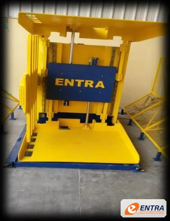
ENTRA pallet inverter (from the ENTRA company profile)
FAMILY // 13 1 interactive 3D models

Accumulation Tables

Accumulation tables that buffer products between machines so a short stop downstream does not stop the whole line.

Description and operating principle

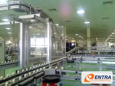
An accumulation conveyor momentarily holds products before releasing them to the next production phase. On an accumulation table, products arrive in single file, spread onto a wide moving bed when the downstream machine slows or stops, and are guided back into single file by rails when it restarts. ENTRA supplies accumulation tables and alpine (multi-level) accumulation conveyors.

Accumulation Table A wide moving bed holds products for a short time when the next machine stops, then guide rails funnel them back into single file so the line keeps running.

Typical applications

  • Bottling and canning lines. Buffer bottles, cans and jars between filling, capping, labelling and packing machines.
  • Machine stop protection. Keep upstream machines running through short downstream stops.
  • Manual packing stations. Give operators a buffer of products to pick from.

Available configurations

  • Accumulation table. Wide modular belt bed with guide rails for mass accumulation.
  • Alpine conveyor. Multi-level accumulation conveyor that stores products in a compact footprint.
  • Bi-directional table. Table that can fill and release in both directions to suit the line.

Main components

  • Accumulation bedA wide moving surface where products build up as a buffer.
  • Guide railsFunnel the mass of products back into single file.
  • Infeed laneProducts arrive from the upstream machine.
  • Single-file outfeedReleases products to the next machine as it needs them.

Technical design basis

Bed width & length
Selected from the buffer quantity and the space available.
Belt type
Selected for the product, stability and cleaning.
Guide rails
Shaped to return products to single file without jams.
Controls
Sensors and logic that fill and release the buffer.

The photo shows an ENTRA accumulation table from the ENTRA brochure. Buffer capacities and speeds are defined per project and are not implied here.
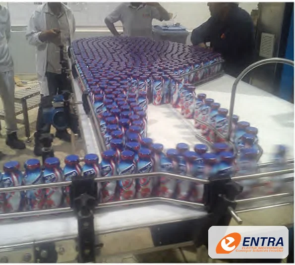
ENTRA accumulation table with bottles (from the ENTRA brochure)
FAMILY // 14 1 interactive 3D models

Conveyor Line Integration & Automation

Integrated conveyor sections, transfers, sensors and control interfaces that coordinate material flow across production equipment.

Description and operating principle

Conveyor line integration connects individual machines and transport sections into a coordinated material-flow system. The engineering scope may include mechanical transfers, accumulation, product detection, drives, PLC interfaces, operator controls, safety circuits and commissioning. Exact automation architecture depends on the existing plant and project scope.

Conveyor Line Integration Conveyor sections, a right-angle transfer, sensors and a control panel work as one line, so product flow is coordinated between machines.

Typical applications

  • Machine infeed and outfeed. Coordinate product transfer between conveyors, fillers, packers, inspection machines and other process equipment.
  • Accumulation and release. Buffer product flow and manage upstream/downstream rate differences.
  • Sorting and diversion. Route products to destinations using suitable identification, sensors and mechanical diverters.
  • Line modernization. Connect new conveyor sections to existing equipment and control systems after interface review.

Available configurations

  • Conveyor line extension. New conveyor sections connected to an existing production line.
  • Accumulation and metering. Controlled buffers and release logic between process stages.
  • Sorting and routing. Sensor-led routing and mechanical transfer devices for defined product streams.
  • Controls retrofit. Targeted drive, sensor or PLC integration based on the installed system.

Main components

  • Control panelPLC, operator screen and signal light coordinate the line.
  • Product sensorDetects each product so the controls can time transfers.
  • Right-angle transferPasses the product onto the next conveyor at 90°.
  • Belt sectionBrings product from the upstream machine.
  • Roller sectionTakes product on to the next process.

Technical design basis

Throughput & cycle time
Defined from product rate, machine cycle, accumulation and shift pattern.
Control platform
PLC, HMI and communications selected to suit customer standards and existing plant architecture.
I/O and instrumentation
Sensor, actuator, drive and safety-device list developed from the sequence of operation.
Safety integration
Risk assessment and interface definition for emergency stops, guards and machine interlocks.

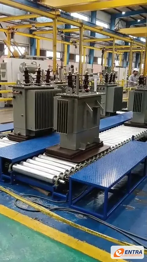
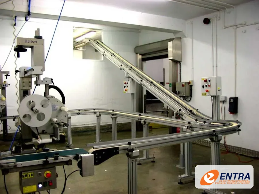
The images are industrial application references from ENTRA’s supplied gallery. They do not assert a specific PLC brand, safety performance level, line throughput or certification.
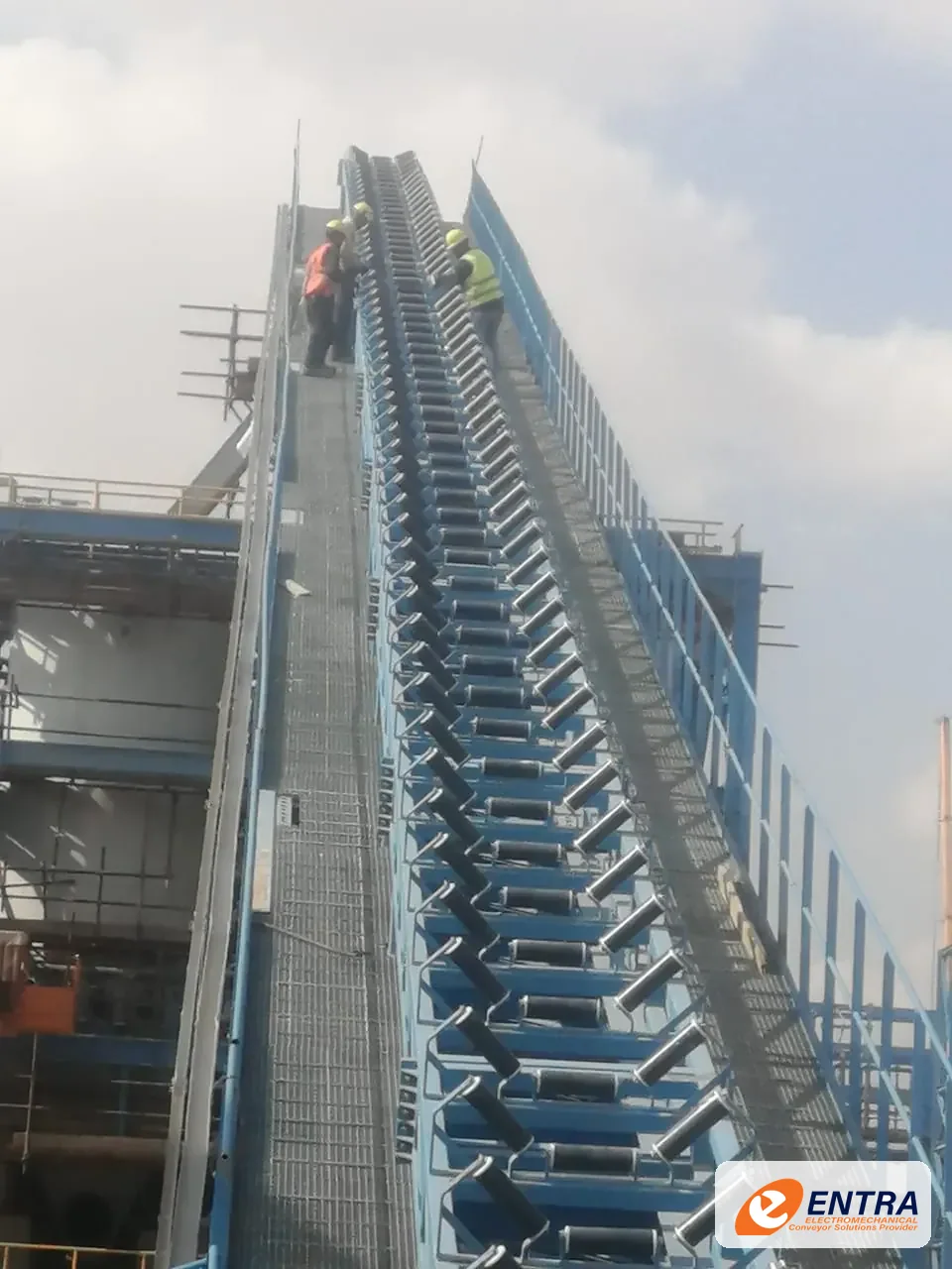
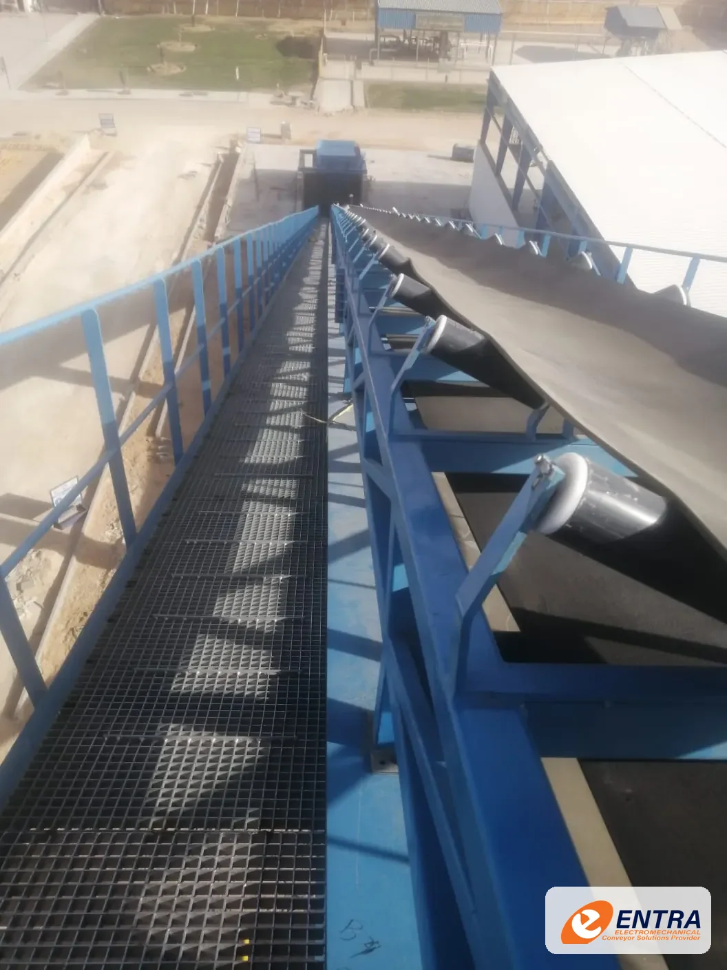
Industrial conveyor application — ENTRA gallery reference Industrial production-line integration reference Industrial material-handling application reference
COMPLETE ENTRA PORTFOLIO COVERAGE

Complementary Structures, Accessories & Industry-Dedicated Lines

In addition to the 19 interactive 3D models and 14 equipment families above, ENTRA’s documented manufacturing scope on entra-eg.com and the MODU V22 platform includes the following complementary engineering categories:

STRUCTURAL & STAINLESS PLATFORMS

Structural Steel & Stainless-Steel Platforms

Standalone and machine-integrated industrial steel and stainless-steel operator platforms, mezzanines and walkways engineered for strength, corrosion resistance and vibration isolation (including multi-stage process platforms).

STRUCTURES & LINE ACCESSORIES

Conveyor Structures, Guide Rails & Supports

ENTRA conveyor support structures, adjustable tripods and bipods, stainless/HDPE guide rails, brackets, drip pans, crossovers and dead-plate transfers matched to your conveyor layout.

MODU V22 EXTENDED SERIES

MODU Stainless (DS/DM/DL/DX) & Slat-Top (STC)

Stainless-frame modular chain and belt series (DS2, DM3, DL2, DX2, DT2, DR2, DF2) and the 4-size STC Slat-Top conveyor range for bottling, canning and hygienic packaging lines.

SECTOR-DEDICATED LINES

Carton, Composite Can, Paper & Pharma Lines

Application-engineered conveyor systems for Composite Can Manufacturing, Carton Handling, Paper Converting, Personal & Pharmaceutical Packaging, Product Assembly and Heavy Bulk/Mining transport.

Photos, 3D models and designs are the property of ENTRA and may not be reused without written permission.

05 · LET’S TALK ABOUT YOUR FACTORY

Tell us what you need to move

Tell us a little about your product, factory and project. You can attach your requirements when you contact us, and our team will help you work out the next step.

How ENTRA Engineers Review Your Enquiry

  1. 01
    Product & Duty Review We verify dimensions, weight, speed, hygiene and environment requirements.
  2. 02
    System Selection & 3D Layout We match the right ENTRA or MODU family and prepare a tailored layout proposal.
  3. 03
    Formal Quotation & Local Support Manufactured and supported locally with ISO 9001, 14001 and 45001 quality systems.
ENGINEERING QUOTATION REQUEST

Send us a message — we’ll help with the next step

Final equipment selection and quotation follow an engineering review of your actual product, layout, capacity and operating environment.