
Container and bin tipping
Tip compatible bins or containers into hoppers, feeders or process equipment.
Product orientation and process handling
Engineered stations for controlled tipping, tilting or reorientation of compatible products, containers and loads.
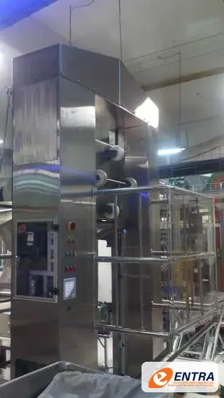
Overview
Tilting and inverting stations change the orientation of a load to support emptying, access, assembly, inspection or process transfer. The mechanism may use a pivoting cradle, powered table, clamp or purpose-built fixture. Product retention and controlled movement are central to safe design.
Tip compatible bins or containers into hoppers, feeders or process equipment.
Rotate or tilt products for inspection, assembly or downstream handling.
Present parts or materials to a machine or workstation at a controlled angle.
Reduce manual handling where a mechanized tilt station is suitable and risk-assessed.
Operating principle
Tilting and inverting stations change the orientation of a load to support emptying, access, assembly, inspection or process transfer. The mechanism may use a pivoting cradle, powered table, clamp or purpose-built fixture. Product retention and controlled movement are central to safe design.
A simplified illustration of the motion — not to scale and not a performance simulation.
Available configurations
Cradle or fixture for controlled tipping of a compatible bin or container.
Pivoting platform to present a load at a defined angle.
Purpose-built retention arrangement to rotate a component or carrier.
Mechanism, guarding and controls designed around the actual product and task.
Technical design basis
These items identify the information used to engineer this equipment. Numerical limits appear only where the referenced catalogue supports them; other values are confirmed for each project.
The gallery category contains tilting-station equipment references. Do not infer a rated load, tilt angle or safety category from photographs; these are determined by the project design and risk assessment.
| Maximum load & centre of gravity | Established from the actual load and fixture, including dynamic effects. |
|---|---|
| Tilt angle / rotation | Defined from process requirements, clearance and product retention. |
| Actuation | Hydraulic, pneumatic, electric or mechanical drive selected by force, motion and environment. |
| Safety & guarding | Risk-assessed restraints, interlocks, access controls and safe loading method. |
Engineering considerations
A useful proposal starts with operating conditions and interfaces. Final sizing is confirmed by engineering review.
Mass, dimensions, centre of gravity, support points, fill condition and containment.
Tilt angle, rotation axis, stroke, travel path, clearances and transfer height.
Clamps, stops, restraints, guarding, interlocks, access and emergency-stop requirements.
Load/unload method, cycle time, operator interaction, sensors and machine interfaces.
Photographs
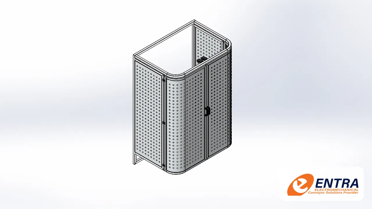
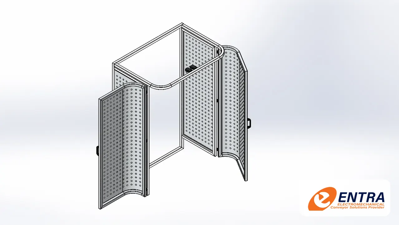
Captions identify the equipment shown; a photo is not a claim that every image is a completed installation of the exact configuration described.
ENTRA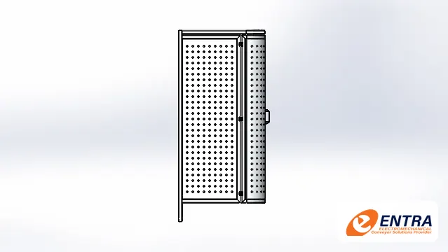 ENTRA
 ENTRA
 ENTRA
Related equipment
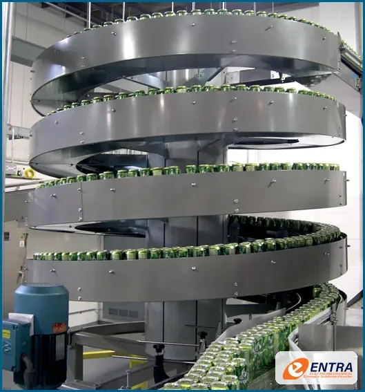
Continuous vertical conveying for production lines that need elevation, accumulation or controlled cooling wi…
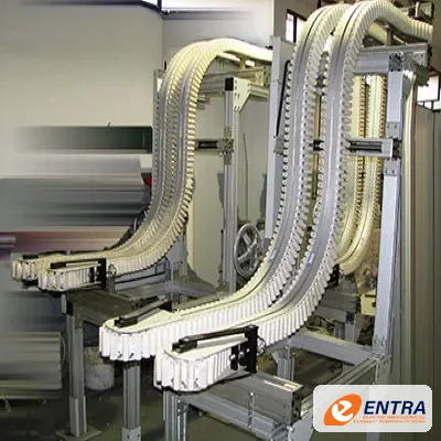
Opposed gripping belts hold suitable products at their sides to move them vertically, invert them or connect …
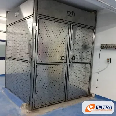
Purpose-designed vertical transfer equipment for moving compatible products or loads between conveyor levels.
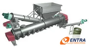
Meter, feed and transfer powders, granules and suitable bulk solids using a rotating helical flight in a trou…
Request a quotation
Share the product, the layout and what the line has to do. An ENTRA engineer reviews every enquiry and replies with questions or a proposal.
