
Carton and tote handling
Move rigid-base cartons, totes and containers through packing and dispatch areas.
Carton and unit-load flow
Gravity and powered roller conveyor arrangements for conveying, accumulation, transfer and distribution of compatible unit loads.
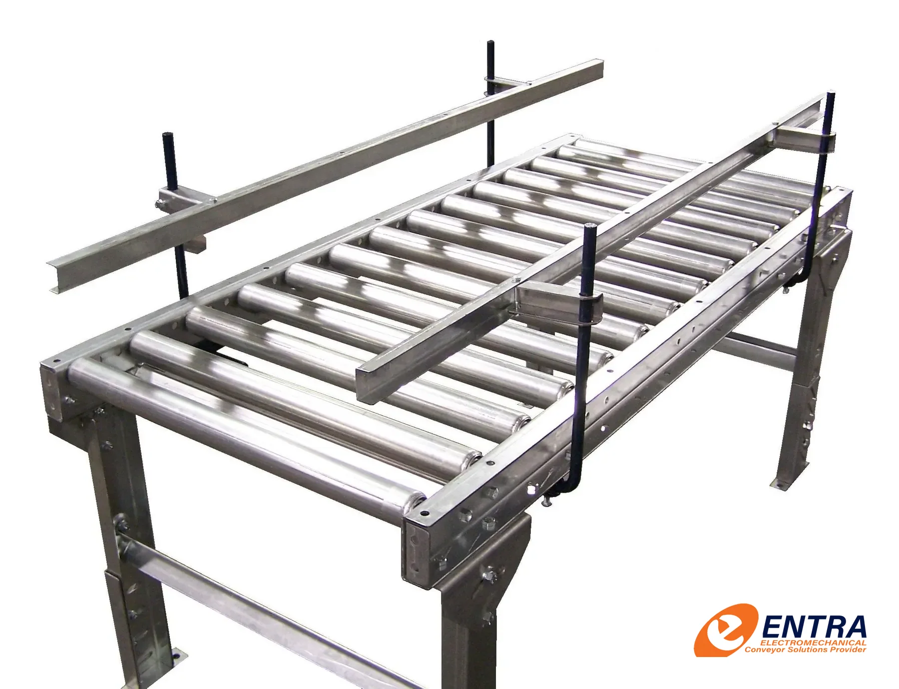
Overview
Roller conveyors support products on a series of rotating rollers. Gravity versions rely on slope and product momentum; powered versions drive rollers directly or through belts, chains or line shafts. Roller pitch, diameter, frame and drive zones must suit the load base and product geometry.
Move rigid-base cartons, totes and containers through packing and dispatch areas.
Buffer products between processes using controlled or zero-pressure zones where specified.
Handle compatible palletized loads using appropriately engineered roller sizes, frames and drives.
Connect conveyor sections with transfer units, stops and diverters designed for the load.
Operating principle
Roller conveyors support products on a series of rotating rollers. Gravity versions rely on slope and product momentum; powered versions drive rollers directly or through belts, chains or line shafts. Roller pitch, diameter, frame and drive zones must suit the load base and product geometry.
A simplified illustration of the motion — not to scale and not a performance simulation.
Available configurations
Non-powered roller bed for compatible products and layouts with suitable slope or manual push.
Motor-driven zones for controlled movement and line integration.
Buffered zones using control logic selected for product and process requirements.
Direction changes and cross transfers designed around load footprint and stability.
Technical design basis
These items identify the information used to engineer this equipment. Numerical limits appear only where the referenced catalogue supports them; other values are confirmed for each project.
Roller conveyor images are from ENTRA’s roller-conveyor gallery. Pallet duty, carton duty and accumulation behavior require different design checks; the same roller layout should not be assumed suitable for every load.
| Roller pitch | Selected so the load is supported by sufficient rollers throughout travel. |
|---|---|
| Roller diameter & wall | Selected from load, impact, span, duty and bearing requirements. |
| Load capacity | Calculated for the actual load distribution, roller count, frame span and support arrangement. |
| Drive arrangement | Gravity, chain, belt or motorized roller solution selected for control and duty. |
| Accumulation control | Zone logic and sensor placement defined by product flow and downstream acceptance. |
Engineering considerations
A useful proposal starts with operating conditions and interfaces. Final sizing is confirmed by engineering review.
Minimum and maximum load dimensions, weight, base stiffness, runners, feet and underside condition.
Roller diameter, pitch, face width, material, bearing type and load distribution.
Gravity or powered operation, drive method, zone length, accumulation logic and speed matching.
Slope, curve radius, transfers, side guides, stops, guarding, access and emergency-stop strategy.
Photographs
Captions identify the equipment shown; a photo is not a claim that every image is a completed installation of the exact configuration described.
ENTRA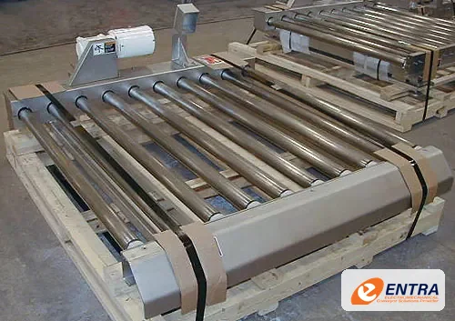 ENTRA
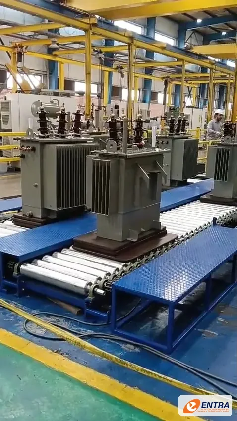 ENTRA
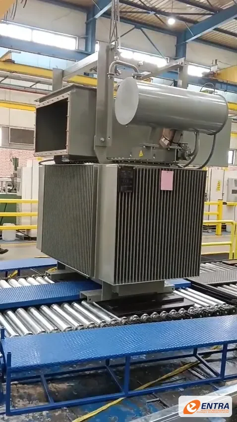 ENTRA
Related equipment
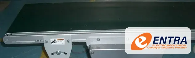
Continuous belt transport for cartons, cases, packaged products and suitable unit loads across production, pa…
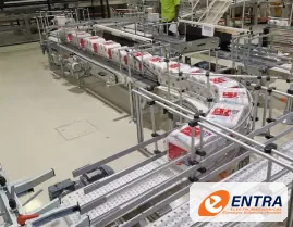
Modular plastic-chain conveyor platforms for compact product handling, straight runs, curves and engineered l…
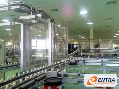
Aluminium-profile conveyor frames and modular structures for production, assembly, inspection and material-tr…
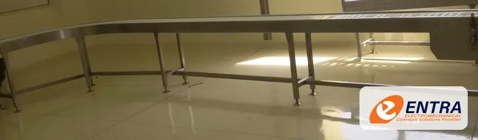
Stainless conveyor structures and conveying arrangements designed around defined product-contact, cleaning an…
Request a quotation
Share the product, the layout and what the line has to do. An ENTRA engineer reviews every enquiry and replies with questions or a proposal.
